 Question: What's that nonsense anyway ?
Good question. Have to quit on that too.
It all started with the simple fact, that a 1973 Nikko STA-5050 Stereo Receiver along with two Arcus Sinus two-way speakers to be used as pure MP3 playback device occupies a large share of room on the workbench. Well - you need to have speakers, since it wouldn't work without them. But this 30-pound unit with 40 x 30 x 15 cms outer dimensions is a pretty big box.
What to do ?
Simple answer: while there is no more room under the table, additional shelves cannot be installed by various reasons, something physically smaller has to be used.
Using the Nikko vertically ? Haha. Come on - let's be serious, won't you ?
Mini Unit ? No. Has to be bought and whatfor if I only need the amplifier of it ?
Active Speakers ? Will have to be obtained too and these 'PC Speakers' are pathetically-ridiculous and sound like shit in most cases. "100W PMPO" - driven by a 12-Watt wall-transformer. Argh - I'm going to barf !
I only wanted - and needed - just a pure final amplifier. One that fits on top of one of the speaker in the best case. While digging in the internet I'd somehow stumbled across an auction at Ebay where they offered a power transformer, stereo output transformer and some tube sockets. I always wanted to build a stereo tube amplifier again for longer.
So I'd bid on that auction and won it. (With pure luck !)
Next 'Digging Orgy': what tubes do I have and what could I do with them ?
The transformers pointed in the direction of 2 x EL84 or EL95. Plus some pre-amp stuff and single-ended design. No push-pull and power above 5 Watts per channel. A bid closer to the bottom of my tube boxes I located two nice looking ECL86 tubes. Some bended pins, one from Siemens and one from Valvo.
The ECL86 are preamp-triodes and final-pentodes in a single unit.
So they are ideal for what I had in mind.
The real excitement started, when the parts arrived. The power transformer has outputs for 170 VAC and 12.5 VAC ... good enough for about 230 VDC voltage at the output transformer after rectification and smoothing. A bit of irritation is caused by the single 12.5 V heater voltage. Two ECL86 needed to be heated in series, even though they are designed for 6.3 V parallel heating. But what - don't want to be too picky. They surely work that way nontheless.
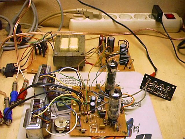
Let's throw together a prototype to get an impression. And we start with the power supply. That's already a good half of the total work and gives a solid basis. About half an hour later I'd got an electric shock from it for the first time.
For the "Low Voltage Diddlers", that play around with 5 and 12 volt only: 230 V DC from a tube power supply are not just 'a minor annoyance'.
That really bites and hurts quite a lot.
So: Watch out ! Really now - no fuss.
(However: 12 VDC also could be lethal. If a car battery drops on your head ...)

How does that power supply look like ? Now - that's no witchcraft. Veritable parts can be obtained in Germany - with the exception of the power transformer - at Reichelt Elektronik.
In most cases ambitious Do-It-Yourselfers have a lot "crapbags" at hand with a lot spare parts to come handy. Here's a circuit diagram:
In the center there's the power transformer. Getting that one might be the most difficult part. It should have about 170 VAC
at ... well ... 100 mA current. That might be a little thin but is sufficient for most cases. More on that later. To the left there is a double pole main switch behind a fuse.
A single pole will work too and a fuse is luxury for cowards only anyway ... but if you accidentially kill a dear friend (or yourself !) with an electric shock or if you start a fire in your house the moaning and complaining will surely start afterwards. So: double-pole and a fuse. Dont't save money at the wrong place.
To the right from the transformer is the rectifier, made conventionally from four 1N4007 diodes. They are capable to handle 1000 V and are rated 1 Amp. We don't need that but they are rather cheap and readily available. Those who always go wrong with the directions or gave up building rectifiers from single diodes may use a generic 4-pin rectifier like the B500C500 or -C1000 or something similar. The rectifier should be ready for (2 * 170 V) * SQR2 = about 480 VDC and rated 500 mA current at least - due to the peak charge current of the filter capacitors.
The filter- or smoothing capacitors are the two 100 µF / 385 V right of the rectifier. There is a 100 nF / 500 V ceramic or polypropylen capacitor parallel to these filter caps that should block high-frequency signals from the DC. The 100 K / 1 Watt parallel to the capacitors is a bleeder resistor that helps discharging the capacitors when the power supply is turned off. Otherwise the caps hold the charge for weeks probably and there is a good chance that you'd get shocked next time you stick your finger into the circuit.
That might be helpful to wake up certain persons - but could end up quite bad too. So: use a bleeder resistor.
That's a minimal version. The amplifier may come a "hummingbird" with it, because the smoothing might be sub-optimal. The 'luxury version' uses 1 nF / 1200 V capacitors (foil or ceramic) across each diode and a uses a 10H choke (Yeah - right: Ten Henry !) in the +230 V line, or a 47 Ohm / 10 Watt wire-wound resistor if the transformer allowes, followed by another 22 µF / 385 V capacitor. Or you build something exotic with an active regulation.
That's what I did not. I didn't want to design a Super-Hifi-Amplifier "disregard the costs", but a small screamer that plays MP3s from a computer soundcard into a pair of midium-efficient speakers in reasonable quality. It shouldn't cost a fortune. Therefore we leave all the finetuning and enhancements for some time in the future. The very cost-sensitive people even leave out the "humdinger" potentiometer in the heater circuit, replace it with two 100 Ohm / 1 Watt resistors with the middle between them tied to GND or simply connect one wire of the heater winding to Ground. In practise it doesn't matter much. Not with the volume levels and output power we're going to achieve here.
More important is the efficient area of the heater wires - 0.5 mm˛ should do - and have the heater wires drilled against each others to avoid stray magnetics around them.
But let's see what else we've got here.

The professionals surely say: "Oh well - fine." and the lesser educated scratch their heads and think 'Now he's gone lunatic.'. Clicked the diagram ? Looked into it ? Understood anything ?
Not really ?
Doesn't matter. I'm going to explain it.
Let's start up front. If you pull the triodes' cathode against GND and use an incredible 10 Mega-Ohm resistor for gaining the grid voltage, this is called "Zero Bias Grounded Cathode" or "Grid Leak Bias" or "Grid Current Bias". Saves some components, enhances the amlification gain and the circuit is - theoretically - lesser sensitive against hum. But the input current is only determined by the grid resistance and the anode current is almost impossible to be tuned. Almost not at all, but let's accept it for now and don't worry about it: in most cases I know what I am doing.
The components on the amplifier have been determined experimentally. Honestly. I needed to adapt the amp input to a soundcard output that has been designed to drive headphones or small "computer speakers" directly. Therefore I had to reduce the input voltage drastically with that 1K resistor. The 10K potentiometer is the volume control of course. The 100nF capacitor is the DC decoupling cap to the triode grid. A 10nF should have done already. In theory the lowest input frequency is below 10 Hz now, but I have a large amount of these 100nF caps. So I used that.
The two capacitors above the triode, the 2K2 / 2 Watt resistor and the 220K resistor determine the triode anode current, which establishes at about 0.48 mA. The caps along with the 2K2 are just filters that stabilize the voltage for the 220K resistor and cause lesser hum at that point.
From the anode we pass the signal to a 100nF to a 680K resistor. This resistor is recommended in the datasheet for use with a grounded triode cathode. The base amplification drops a bit and the output pentode won't clip that early. A 1K resistor is a current-limiter for the pentode grid input-current.
The 4M7 resistor between triode anode and pentode anode is a frequency-independent feedback. There is no feedback from the output transformer secondary back to the triode input. I'd left it away, because it louses up the sound and is pretty tricky to do with that kind of input stage.
The idle amplification of the triode stage should be at around 65.
While the output transformer is no "Ultra-Linear" type, which offer a separate wire for the screening grid (grid 2) at the pentode, we have to look for some other solution. From the smoothed triode anode voltage we pick another 4 mA for the grid 2. That's sufficient for a good stability and uniform amplification.
In that case we use the circuit, as shown for "G2 Fixed Mode". In the meantime I got a pair of transformers that have 7K total with further leads to 1K6 (and 3K3). It was a good occasion to wire up G2 to that 1K6 winding and see what happens when the output tube runs in true "Ultralinear" pentode mode. From version 1.1F I'd included that as well. More on that later.
The pentodes' anode is hooked to the 'lower' end of the output transformer, as usual. The 2200 pF / 1000V capacitor shorts out high-frequency signals. You may have it, but it is not neccessary. I also have a batch of these ... something in the range of 330pF - 3n3F will do as well, given it is rated for a voltage of at least 600V.
Up to there it is all "Classical Tube Technology". But then something unexpected can be discovered.
Usually a 180 Ohm / 1 Watt would be sufficient as a cathode resistor for the pentode, which is then AC-wise bypassed with a reasonably large capacitor. The voltage between GND and cathode will establish somewhere in the 6 - 8 VDC range, but will not exceed 12 VDC, so something from the transistor-radio corner should do. It might be recommended to use a 105°C type, because a tube amp may get a bit warmer inside.
Now there is that voltage regulator chip - surrounded by some little crap and a trimmer in addition.
Background for this arrangement is, that most of the tubes accidentially picked from some crap-box might be pretty much worn out already. At least there is a good chance that two picked with no attention are anything but matched and give different ratings. So you will have to adjust them for best match. A fat trimmer of 220 Ohms should do to. Sure. But once you'd changed the tubes you will have to re-adjust the cathode current once again.
This circuit is a constant-current source, which is adjusted via the ratio of Ureg to the total value of the resistor network behind the regulator. For this layout the output voltage of the regulator is about 2.5 Volt. Which regulator you have to use depends on the tube. The EL84 usually work fine with the 7805. But on these tubes the regulation range on a 7805 would be too small. Therefore I'd picked an adjustable regulator of the very common and widely available LM317 series - or its "Low Drop Regulator" cousin LT1084 respectively. The output voltage is set with the resistors R1 and R2 to about 2.5 Volt, so that a practical regulation range can be achieved with generic standard parts. In that setup the range is 22 - 45 mA. If you leave away R13 (270 Ohm) you could extend the range to 14.5 - 45 mA. There is a lower constant of 12.5 mA permanent current flow through R1 and R2. If you use 120 Ohms resistors here the "base current" can be reduced to 10mA, but these series of regulators should not run below 10 mA due to stability issues. The resistor R12 (75 Ohm) sets the maximum upper current "around the outside". The 10µF capacitor over the output is a "Must" on this type of ground-free regulators.
The current through the load resistors is calculated by the formula
Uout = 1.25 * (1 + (R2 / R1))
The overall resistance of the resistor entire network varies - calculated - between 54.5 Ohm (Trimmer at 0 Ohm) and 111.2 Ohm (Trimmer to 500 Ohm). Therefore the current through the resistors is adjustable between 45 - 22 mA ... and while the regulator loads the input voltage in a proportional ratio the same current flows through the penthodes' cathode too - disregard, how "good" or "bad" it is already.
A brand-new ECL86 should easily be capable to deliver 38mA current through the cathode - according to the datasheet 55mA are the absolute maximum rating. 28mA are a good compromise and are within the operational area (if you can read diagrams ...). Is it impossible to get the tube tuned to 28mA its "emission capability" is gone down that low that the tube is only good for crap or as display sample in a collection.
Let's assume that everything is fine that way.
During my experiments and various reworks I'd tested around with lots of tubes and output transformers. Here this "Auto Bias" circuit has prooved its quality, since the cathode current never changed - except I wanted it to change. With Revision F I'd introduced the 1.00 Ohm resistor R11. If you measure across this resistor the voltage is 1:1 proportional to the current through it. If you measure 28 mV there is a 28 mA current flow.
Hint: When you build up your own amplifier, you might fed +5 Volt from an external source to tube pin 7 and measure the voltage across R11. Set it to 28 mA and you're done with the adjustments. Once you reached the "hot phase" with the tubes installed there is nothing that could go wrong anymore.
Please allow me some helpful comment at this place.
Common Ground: Amplifiers are built best around a fat, common ground in the center. Particularly on 'handwired' units there is nothing more important (after sufficient voltage- and power-handling capabilities of the components) than a central grounding point. It helps to avoid oscillation of the circuit and blocks the distribution of hum and noise.
 Universal Heating: With the prototype I'd built the heating to be used with two ECL86 in series (6.3V - 0.66 A) as well as two PCL86 (13 V - 0.3 A). At them moment I use two PCL86, which are connected to the 12.6 V heater voltage in parallel heating. They are a bit 'underheated' with that, but that is of no major importance here and doesn't matter much. Universal Heating: With the prototype I'd built the heating to be used with two ECL86 in series (6.3V - 0.66 A) as well as two PCL86 (13 V - 0.3 A). At them moment I use two PCL86, which are connected to the 12.6 V heater voltage in parallel heating. They are a bit 'underheated' with that, but that is of no major importance here and doesn't matter much.
PCL86 are usually significantly cheaper than ECL86, because they had been used in pretty profane TV audio stages, while the ECL86 come from radios and HiFi amplifiers.
When using two ECL86 I have to cut the line, which connects the two Pins #4 of both tubes. The pins +5 are tied together anyway. In the PCL case I feed 12.6 V to the points H and H', which are Pins 4-4 and Pins 5-5 on both tubes (parallel). In the ECL case the pins 5-5 are tied together, H is connected with Pin #4 of the first tube and H' with Pin #4 of the second one. That was it. Pretty variable. Anyone needs a drawing ?
Well - okay, don't want to be to sparse. Here's the actual Super-Luxury-Version with a switch. You'd better not install ECL86's when the switch is set to 'PCL' 12.6 V across a 6.3V-heater is no good idea ... other way round the PCL86's will survive, if they are fed with only 12.6 V in series, which would give 6.3 V at each heater only.
If you use DC-heating or have one wire connected with GND on AC-heating, make sure you'd picked the one to heater pin 4. That will enhance the insensitivity agains hum and is caused by the tubes internal design. The datasheet mentions this on page 3 - close to the bottom under "Hum".
A Delay for the anode voltage is recommended on tube amplifiers with solid-state rectifiers. It helps to extend the tubes' lifetime. Usually the high voltage should come up about 10 seconds after the heater voltage, when the heaters are already glowing. On units with tube diodes this process is achieved automatically due to the build-up time of these diodes before they come conductive - with solid-state rectifiers the high voltage is applied to the tube anodes within fractions of a second after the smoothing caps have fully charged at power on. There are however different opinions existing on the efficient use of it in daily practise. Those who think they cannot live without it may go ahead and add a delay to the circuit. A delayed current or at least a current limiting is also useful on the heater circuit. The cold resistance of the heaters is very low and the cold current draw is pretty high. Heater resistance is at about 1 - 2 Ohms - and the tubes light up bright yellow for about half a second. This would be a topic on an optimization. If you like.
Output Transformers (OT) are pretty rare in the meantime. If you find something suitable for a single EL95, EL80 or EL84 "Single Ended" it will surely work (somehow) with the ECL86. With my OTs the DC (Ohm) resistance at the primary winding is about 500 Ohms, the secondary is about 0.5 Ohms (hard to measure). If you calculate the output (speaker) impedance at 4.5 Ohms at 1 KHz, the primary impedance is about 5 KOhms given a transformer ratio of 100:1. This is about what you need for a single-ended EL84. A simple calculation example on the real-existing prototype unveils the following: testing for the OT DC current reads 28 mA, with that the voltage drop across the OT primary is 14 Volts. 14 divided through 0.028 Amps is 500 Ohm - the DC resistance. If we assume to have 232 Volts at the input of the OT, 218 V at the anode of the output pentode and about 6.5 V on the pentode cathode the voltage drop across the tube is 211.5 V. At 28 mA current trhough the tube the internal resistance is 7.5 KOhms - if we leave out the grid currents here for a while. And that is reasonably well positioned within the operational range..
With these values a transformer specialist like Firma Reinhöfer could do something. Pretty sure that they have something appropriate in their lists, for the EL84 most likely. The OTs from Reinhöfer look very nice, are made superbly ... and cost a bit. That's something you won't get in the WalMart around the corner for 5.95 bucks. We'll have to accept that.
During my experiments I got two transformers from off Ebay that have further connects at Zp of 1K6, 3K3 and 7K. Usually a ratio of 33 percent of the total primary impedance is used for an ultralinear design. That would be about 2K35 from a Zp of 7K. But I'd tried, what happens if you tie the grid 2 to 1K6. Result: the bass range got way more dense, the amp clipps way more softer and sounds pretty balanced over the entire spectre. Of course these output transformers had a totally different characteristica right from the start, but I deeply tested them in triode mode as well as in "real pentode mode" and the latter one is far more appealing. Sounds rounder and defined. So probably it is not the worst idea to look out for some ultralinear-capable transformers while flipping through the internet pages. Transformers intended for the EL84 single-ended faily often have a wire for the G2. It pays to experiment with these.
Something else on the power supply: The transistorheads install large capacitor "batteries" in their gear - and that should do the trick. Bullshit and waste of money. On request they will surely be able to give 'good reasons' for that habit and talk you down with their gibberish (Stop listening if they come up with 'impulse power' 'reserves' 'transient response' etc.). Let's stay realistic and let's assume that a circuit running within its design limits and at a certain reasonable peak power has a definite current load. This current causes a drop of the supply voltage along the resistance in the transformer windings and wiring - up to a point where the smoothing caps can no longer balance out the current spike. This is a physical law and we cannot do something against that. As a rule of thumb designers calculate a capacitor of about 1.000 µF per 1 Amp current drawn. The above-mentioned circuit pulls about 60 - 75 mA in the stereo version. So a 100 µF capacitor were sufficient. If we add some more reserve (without exceeding the diode / rectifiers peak current at power on) - and you still have hum.
Why ? Because the hum noises at 230 VDC have a way higher peak-to-peak value than at e.g. 5 VDC.
In the percent-value it might be within the same range, but 10 V pp cause a lot more 'turbulences' in the active components than 0.1 Vpp.
So it is recommended to wire in a fat choke in the DC output and add a further 22 - 100 µF behind. That smoothes quite a bit. 5 - 10 Henry are a good starter value. If the choke is capable to handle 0.5 Amps ... even better.
However: the guy in the parts shop round the corner may give you some puzzled look if you ask for such a beasty. For these guys today a line-choke with 1 Amp and 10 mH are already considered to be a big piece of hardware they don't stock any longer. What to do ?
Check your basement and see if there is a left-over transformer with 30V / 1 A. These had been part-of-choice for those stupid "regulated bench power supplies" in our earlier years. The secondary side has an inductance in the Henry range. We don't need the primary. So it doesn't matter if the transformer is shot - which happened regularly in the good old days, when we were younger and dumber. These transformers rarely burn out on the secondary - thicker wire, more reserves. They are dead as transformers, but might still serve as a choke.
Just check it out. The voltage should drop less than 5 V, but that may reduce the hum significantly.
The idea itself isn't very brilliant - confessed, because there are some differences between transformers and chokes (particularly on DC-chokes), but may be some sort of substitution until a real good choke comes our way.
BTW: those neon lamp / flourescent lamp chokes may work well too.
Power transformers for the truely desperate. Assumed someone really wants a small tube amp and cannot find an appropriate AC power transformer. Not for good words and money - except, probably a lot money probably ... we could build our own substitution transformer.
Warning ! This solution is for the truely desperate only, for emergency or wartimes and if there is no other way out.
It is not applicable or recommended for people that build up nicely designed cases first and look for matching parts afterwards.
What do we need ? A high voltage at about 170 VAC and - let's say: 150 mA, plus a heater voltage of 6 VAC and gracious 2 Amps, alternatively 12 VAC and about 1 Ampere. The latter one is the least problem. The electronic shops have tranformers with 12 or 15VA power and 12 V output voltage by the dozen. So many that they have to sell them. This part could be considered as solved quite fast.
For the high voltage we need to be ingenious and calculate a bit.
170 V multiplied with 0.15 Amps are 25.5 VA ('Watts' for the traditionalists that cease to adopt the IEC units). Breaking it down to 230 VAC - 25.5 VA / 230 V = 0.111 Amps. And let's calculate 230 Volt / 170 Volt = 1.35 : 1.00. That means: a transformer that converts 230V line AC down to 170 VAC has a ratio of 1.35 : 1 and picks up 0.111 Amps .... divided through the (very optimistic) power factor of 0.9 at 90% efficiency = 0.122 Ampere.
That's exactly what we have not. Instead we simply install two transformers back-to-back with their secondary windings. The first transformer is hooked to the line AC, the primary of the second one is our high voltage source.
We have - for instance - a transformer with 230 V input and 30 V output at probably 2 Amps (equals 60 VA power). 30 Volt idle voltage multiplied with the transformer ratio of 1.35 results in 40.5 Volt. If we wire a transformer with 40 V / 1 Amp with its secondary to the 30 V output the voltage at the former primary will then be at around 170 V AC. Everything is possible that equals a 1.35 : 1 ratio: 12 Volt 16 Volt, 16 Volt to 21.6 Volt, 24 to 32.4 Volt ... or which comes close to these ratios.
At a ratio below 1.35 the output voltage will be higher, if the ratio is above 1.35 the output voltage will be lower. Simple, eh ?
Please keep in mind that the total power of the driving transformer needs to be higher than that of the driven one. Or else the driving transformer may start going up in smoke when the overall load exceeds its capabilities.
Sometimes there are bargain sales on these 'experimenting transformers', which have outputs at 12, 15, 20, 24, 30 and 40 Volt or at any 1 Volt or whatever. These use to have 30 to 40 VA power and two of them might be handily available and go for rather cheap.
As said: this is just an emergency substitution for a real transformer. The efficiency is lousy, because we have to magnetize two transformer cores and we have the losses on two transformer winding systems and therefore loose a couple of watts anyway - but we will get out 170 V one way or another.
You need to have sufficient room in addition. Transformers with 25 - 40 VA are not just small - and you may need an additional 12 - 15 VA heater transformer too.
In case of doubt you'd better check in at Uncle Reinhöfer - he may sell you a well-suiting, professionally made transformer for your money.
Epilogue: How does it sound and why is the thing called "Cookiebox" ?
Now, you cannot argument about taste. For me it sounds pretty transparent and dynamic. Not really techno-capable, the efficiency and power drops into the bottomless below 80 Hz - as a result of the pretty small Output Transformers.
Power-wise I would say that the output is a good 3 Watts sine / 4 Watt peak or about. The Arcus Sinus speakers are all-closed 4 Ohm 2-Way units with 40 / 60 Watt maximum power, they have a 150 mm Low/Midrange system and a 25 mm dome tweeter. Which disqualifies them already for Techno or other "Wham-Bamm" music of any sort. I'd checked their acoustical levels provisorically and that resulted in about 87 db/Wm, which is a good average for that class of speakers. With the "Cookiebox" the two could produce a fairly loud output. But that wasn't my intention at all. At the moment there is a well-mixed program of MP3s running that contains a hell of titles from my wikl teens (70's and 80's): Pink Floyd, Mike Oldfield, Dire Straits, a little bit of modern stuff, Rammstein for instance or Chris Rea (heared "Stoney Road" a while ago) ... and ocasionally a little bit of Rave / Trance / Ambient.
Well - I'm only 42, which is not meant as an excuse ...
Frequency range, THD, distortions, total bandwidth .... just can say: existing. If it were of any significance to me, I'd had shown you the diagrams here already - if only to show what kind of "Daredevil" I am, to get that done. But I'm not doing that. Doesn't find my interest and I'm not that kind of measuring fetishist (fascist ?) at all. More important that I'd did it, built it and it doesn't sound too evil.
It does not of course. Nice dry base, pretty brilliant mids and quite crisp in the treble range. While playing classical stuff the flutes and violins differ pretty good and are locateable on the stereo basis. Organ concerts loose the subsonic basses of course. A good played Boesendorfer "Imperial" concert piano makes the amp rumble - and basically sounds no different to a Steinway concert piano
(Hahaha - good joke, right ? As if I could tell the difference between the two soundwise ...)
Up to the medium volume level the sound is fairly good. Towards the end of the power spectre the small OT area and the missing current to the speaker, lack of damping factor ends the fun with some hefty distortions. That's the point where the OT is fully saturated and changes of the signals won't come through anymore. Bad luck.
Ah - well: Cookiebox.
Need to explain that too. The original concept included to install the entire amplifier in an old tin cookiebox. I had the choice between a round one (Aldi "Danish Butter Cookies") or a rectangular one from Bahlen dated into the 50's. These two would have nicely fit on top of one of the speakers. But it turned out that both would have been too small. And in the case of the antique Bahlsen box it would have been a shame to ruin that box for this purpose. I will have to build an own case at some time.
The project designation "Cookiebox" however stuck to the little screamer.
Just accept it.
Epilepsielogue: What's next on the schedule ?
Well. I still have a quad of RCA 6Y6-GT "Beam Tetrodes" and a pair of OT's for two EL34 Push-Pull (without Ultra-Linear). I found a circuit on Jogis Röhrenseite that shows a "Cathode-coupled Push-Pull Amplifier" with these tubes. The antique pre-WW2 steel-socket EF14 Pentode in the input will be replaced by an octal russian-made 6AC7 and the Rimlock-EF41 in the intermediate stage might be substituted by a noval EF86 or EF89.
Or I replace the two single pentodes against a PFL200 Dual-Pentode. Something creative and innovative that could only be breeded out by a mad genius like me ....
Let's see if and when I find the time to get busy with that.
Feedback. Reaktions from the Community and Upgrades
The best that could happen to an author, who puts his crap on public display, are readers comments, that show up occasionally. Here is one of those (in German !).
And of course there is a steady process of modification and upgrading.
For testing purposes I reworked the Cookiebox to DC-heating.
Accordingly there is a circuit for that delays the anode voltage.
The diagrams can be found here
S.o.C. - Son of Cookiebox
The child of the cookiebox. Similar scheme - same nonsense. More of that is here !
|